Mk2 Repeater controller
14th November 2009
As the last batch of Rev C PCBs was sold I took a look for any sensible changes I could make for a future revision.
The result is the MK2+ controller.
The main change from the basic Mk2 is that the 24C02 EEPROM has now been replaced by an ISL12027 combined Real Time Clock
(RTC) and EEPROM. This change will in due course allow me to add some minor new features, specifically:
- When idle beacons will be syncronized with the RTC.
- An NMEA0183 interpreter will be added to the software to allow the RTC accuracy to be maintained by a GPS receiver.
- An option to send serial commands to an optional external voice beacon PCB will be added.
For the time being functionality remains exactly as the Mk2 RevC running software Rev 1.59.
The new features will be added, tested and released over the coming months.
Mk2+ owners will be offered upgrades at a nominal fee (sufficient to cover postage) as they become available.
Documentation & Pricing - Mk2+ Rev A
| Document |
|
|
Format |
| Builder's Instructions |
|
|
PDF |
| Programming the Controller |
|
|
PDF |
| DTMF Control |
|
|
PDF |
| Controller Alignment |
|
|
PDF |
| Controller Connections |
|
|
PDF |
| Price List |
|
|
PDF |
| CTCSS Tones |
|
|
PDF |
| Top Down Overlay (Layers 0 & 1) |
|
|
PDF |
| Top Down Overlay (All Layers) |
|
|
PDF |
| Bottom Up Overlay (Layers 8 & 9) |
|
|
PDF |
| Bottom Up Overlay (All Layers) |
|
|
PDF |
| Schematic |
|
|
PDF |
|
|
10th January 2009
During the build of the new GB3EE repeater (see the GB3DY,EE and RB section of this website) it occurred to me that I may be able to somewhat simplify the Mk2 controller.
The FX805 sub-audible tone processor requires a clock of 4Mhz, this has since the first revision of hardware been provided by a 4Mhz crystal and associated 33pF capacitors. However the 8051 family of microprocessors provide a clock signal on the ALE pin of 1/6th of the CPU crystal frequency whenever the CPU is executing internal code.
Since the Mk2 controller does not make use of external data memory and since the CPU clock is 24MHz a 6Mhz clock is always available on the ALE pin. As a test I linked the ALE output (pin 30 on the CPU) to the FX805 clock input (pin 2) removing the 2 x 33pF capacitors. This modification seems to work well, the main effect is a reduction in component count by 3 and a cost saving of about £2.
I recommend that this modification should be done to any new build controllers, the next batch of PCBs will be modified to remove the 4Mhz crystal and its associated capacitors, making the whole thing a bit neater and cheaper.
17th September 2008
For the last few projects I have developed I have used a small batch PCB production service, this service provides small quantities of professionally manufactured PCBs of up to 8 layers. It seemed sensible to update the Mk2 controller to use a more professional PCB. Whilst I don't need to go to 8 layers for the Mk2 controller, by using 2 layers I have been able to remove all wire links. The cost of the PCB is considerably more but I think the extra convenience of a pre-drilled and through-plated PCB is worth the money.
I've also taken the opportunity to change the design slightly to use a Max7480 filter IC by Maxim in place of the rather expensive LTC1063 by Linear Technologies - to some degree this offsets the extra PCB cost. Falling manufacturing costs for multilayer ceramic capacitors now make it sensible to replace the 10uF electrolytics with SMT 1206 outline multilayer ceramics, the only remaining electrolytic types are the 2 x 22µF parts.
Finally as a result of valuable feedback from early Mk2 controller builders, in particular Dominic G7NPW and Peter EI4JR, I have incorporated some minor changes to make the controller suitable for various different radio hardware. Specifically options are now provided for either polarity of mute input and network key input, an option to present network busy out at RS232 levels is also provided, finally provision is made to fit 22t preset resistors in the uncommitted op-amp and discriminator op-amp feedback paths.
The new hardware is designated G1SLE Mk2 Revision C.
The microcontroller code remains compatible with all revisions of hardware.
New construction details, overlays and schematics and part/price lists are here.
Documentation & Pricing - Hardware Revision C
| Document |
|
|
Format |
| Builder's Instructions |
|
|
PDF |
| Programming the Controller |
|
|
PDF |
| DTMF Control |
|
|
PDF |
| Controller Alignment |
|
|
PDF |
| Controller Connections |
|
|
PDF |
| Price List |
|
|
PDF |
| CTCSS Tones |
|
|
PDF |
| Top Down Overlay (Layers 0 & 1) |
|
|
PDF |
| Top Down Overlay (All Layers) |
|
|
PDF |
| Bottom Up Overlay (Layers 8 & 9) |
|
|
PDF |
| Bottom Up Overlay (All Layers) |
|
|
PDF |
| Schematic |
|
|
PDF |
|
|
20th May 2007
With many manufacturers withdrawing products and introducing new ROHS compliant product the time has come for a price review of the Mk2 controller.
I'm afraid that many manufacturers have taken the opertunity to use ROHS to justify a price rise, maybe this is justified by higher manufacturing costs in some cases and maybe it isn't, but with costs going up, in some cases dramatically I have had to pass on these increases. The bottom line increase is around 10% which I suppose isn't too bad.
The new price list comes into effect immediately and is available by following the link at the top of this page.
I will continue to review my prices from time to time as the cost of parts changes, passing on any changes (up or down) as they happen.
16th January 2007
A fair bit of work has been done since the last update adding some new features.
The most 'visible' change from the user's point of view is that the keeper can now select when the repeater's CTCSS encode
is switched off, either immediately the mute shuts, just after the signal report or just after the pips.
There have also been a number of additional features on DTMF decoding behaviour.
See the programming instruction .pdf for full details.
31st October 2006
Well I guess the last update was just tempting fate. A few days after the last update I got an enquiry from a group in Ireland.
Apparently over there repeater callsigns are 7 characters long. With a space and CTCSS letter appended that makes 9 characters in total, one more than the 8 allowed by my software. Version 1.54 is now in beta testing and allows callsigns of up to 15 charcters, which has got to be enough for anybody - errm hasn't it? ...
3rd October 2006
Hopefully this will be pretty much the last update on the MK2 controller.
Software development is complete, barring fixing any bugs that may show up as more MK2 controllers are deployed. It only remains for me to thank my beta
testers for their patience and constructive input during the very lengthy process of debugging and adding new features to the software. In particular I must thank
Dominic G7NPW and keeper of GB3DC. When I thought I had finished Dominic came up with a long list of extra features he thought I should add. Not content with simply
throwing in ideas he patiently tested my attempts to implement his ideas and accurately reported the problems when they happened.
These extras, mostly added after I had thought the job was pretty much done have, I think, made the Mk2 amateur repeater controller something really special.
26th June 2006
CTCSS is a standard, and like all the best standards there are several variations on it. Most decoders support a list of 38 tones, this list normally includes
100Hz as a tone, but many european manufacturers advise against its use, since it has a pretty obvious harmonic relationship with 50Hz mains. Some manufacturers
even go as far as to remove it from the list of 'standard' tones.
More recently some manufacturers are slipping in extra tones, especially on more modern decoders where stability is good and decoder bandwidth narrow. In order to
clarify the situation the G1SLE 'standard tones' are here.
18th June 2006
During the last month I have continued to add new features and refine operation of the controller.
The first major feature is to add routines to help combat abuse of Echolink. Unfortunately every repeater has abuse problems to some degree, the provision of
extra facilities such as Internet connectivity seems to make such well equipped repeaters more of a target for abuse. With this in mind some basic anti-abuse
measures have been added to the Mk2 controller. It would probably not be wise to expand further on these facilities here. I will therefore provide full details
of these anti-abuse facilities only to repeater groups ordering at least a processor + software from me.
The next feature added is a separate timeout for the network key input. An observation was made that since Echolink runs on MS Windows the possibility
of unpredictable behaviour exists! Dominic apparently had a problem with his Echolink PC some months before GB3DC went on air, the PC locked up with its TX
key output active. If this problem had happened on GB3DC the repeater would have timed out and been taken out of service until the fault was cleared. Though
this is a 'safe' situation it seems a shame to disable the repeater just because the network node is unavailable. With this in mind a separate timeout has been added.
If the network key remains active for longer than this timeout it will be disabled until it becomes inactive. This means that the repeater (minus Echolink node) can
be returned to service to handle local traffic. To warn users of this situation the pips following the signal report are replaced by T's (dah) until the problem is cleared.
Another more subtle change has been made to the network busy output operation. Previously the network busy output was not driven whilst the network key input was
active, this meant that if a radio user began transmitting before the internet connected user had finished the busy condition would not be signalled by pulling the busy
output low, received audio would not be routed to the network and the over would be 'lost'. In the latest revision of software the busy output remains active at all times, preventing this problem.
It had also been noticed that if a user took a very short over whilst a beacon was being sent the resulting signal report and tail pips would be inserted in between
the characters of the beacon text. The new software suspends tail pips and signal reports until the beacon text has been sent in full.
Development and testing continues, though I am now getting pretty close to the bottom of the list of desirable features, so I expect to stop adding new features probably at the next update.
21 May 2006
During the last few weeks development of the controller has continued more slowly. The first controller in use on a 'real' repeater GB3DC has proved very successful.
Thanks to patient assistance from the keeper Dominic G7NPW a number of small bugs have been trapped and eradicated.
I am now working on adding a few 'extras' to the software to further enhance the functionality. These additions have required a minor change in hardware. The 89S8252
processor that I originally used has 8k of code space and 2k of EEPROM. The added code caused me to reach the 8k limit. Atmel does produce a couple of alternatives, namely
the 89S5253 which has 12k and the 89C51ED2 which has a full 64k. However, availability of both these parts was problematic, so I began to look further and soon found the
89C55WD (20k) and the P89C58X2 (32k). However, neither of these alternatives provides onboard EEPROM. I have therefore made a minor change to the hardware adding
an external 256x8 bit I2C EEPROM. This change allows a much wider range of processors to be used whilst increasing the available code space to at least 12k.
Once this modification was in place I began to work on new features. The first new feature added will be particularly useful to groups building repeaters connected to Echolink.
GB3DC is Echolink connected and Dominic was finding that the 'soft DTMF decoder' provided with Echolink was less than 100% reliable, with some users having real difficulty in dialling.
I have now added a routine to use the onboard MT8870 DTMF decoder with Echolink. The decoder was originally provided simply to provide remote control of the repeater, however it now
operates as follows.
If the repeater is busy (ie. Accessed and passing traffic) any DTMF decoded by the MT8870 is sent to the serial port with an appended space (ascii 32). All valid DTMF digits 0-9, A-D,* and #
are decoded and sent to the serial port. This format (digit + space) is supported by Echolink and Dominic reports a big improvement in DTMF decoding reliability compared with the
Echolink soft decoder. Remote control functionality is retained with the addition of a remote busy input. The previously 'reserved' input is now used as remote busy - DTMF decoded
with the remote busy input pulled low is assumed to be a remote control command, and is not sent to the serial port.
Further additional features will be added and tested over the next few weeks. Any groups using the board while this additional development work continues will be offered a
free software upgrade once the development is considered 'done'. Kits remain available during this work and even without these additional features the G1SLE Mk2 controller
remains one of the most capable controllers available.
3rd March 2006
It's been a while since the MK2 controller page has been updated, but this does not indicate a lack of progress!
Since the last update 3 boards have been built and tested by beta testers.
This has exposed a silly bug in my code which was preventing the access feature byte from being programmable from the serial port.
This was due to me not removing debugging code, resulting in the relevant address in EEPROM being set to 255 whatever the user selects.
A request was also made for selectable mute input polarity.
Many base stations apparently provide a signal that is +ve when the mute is open, the Mk2 controller was originally able to accept only a signal that is low when the mute is open. A minor change to the PCB artwork has now been made to add an option for +ve mute input. This is provided by optionally replacing the diode on the mute input with an NPN transistor configured to invert the input signal.
Whilst making changes to the PCB I took the opportunity to remove the unnecessary PNP transistor which has become redundant due to a minor software change.
A request was also made to make the 'kerchunker' timer keeper programmable.
This is the timer which required the repeater to be accessed for at least 5 seconds before a signal report, tail pips and ident beacon was sent.
The kerchunker timer is now keeper programmable from 1 to 10 seconds.
A request was also made to use the reserved output as a busy signal to the network device. This has now been implemented, the
repeater busy output goes low when any valid busy signal is detected on the repeater input.
Mainly thanks to my 3 beta testers, the controller is now pretty much ready for sale.
If you are interested in using my Mk2 controller in your repeater please use the contact me form on this website.
26th December 2005
Well, the Rev B board arrived on the 21st.
Maybe it's just the practice from building the Rev A board but this one seemed to go together very easily. Since I managed to
retain the same connection ordering on the 25 way d connector the new board just plugged in replacing the old Rev A one. It was
just a case of setting up the desired levels.
Interestingly I did have a bit of an accident with the new board, I accidentally fitted a 7815 regulator in place of the 7805.
This error resulted in the 13.8volt supply being passed directly to the board, which of course didn't work. Since all the chips on
the board with the exception of the LM324's and the NE567 carry an absolute maximum voltage rating of 5.5 volts I assumed
that this mistake would have cost me an FX805, MAX232, LTC1063 and an 89S5252. Given that these are the most expensive
chips on the board I winced a bit! Surprisingly later testing shows that amazingly everything survived, though I really would
recommend that you "don't try this at home!"
The rev B board is just about right, however I have made some further very minor changes to layout. This was mostly to
clear some space around the 7805 to allow a small heatsink to be fitted if required. Since I've not made any changes to the
circuit, only to the layout I've designated the new board as Rev B1.
This should now be the final revision. After the Christmas holiday I will order a small quantity of Rev B1 PCBs, which I expect
to have ready for beta testers by mid to late January. Whilst I wait for the first batch of B1 boards to arrive I'll get on with
producing assembly instructions for the beta testers, once the instructions are ready I'll publish them as PDFs on the website.
10th December 2005
I've now tested pretty much all the functions of the new controller.
The DTMF remote control works fine, allowing the transmitter to be remotely disabled but also allowing
each method of access / busy detection to be switched off. The auxiliary (or network) audio input also
works fine as does the network key, signalling busy to the network is just done with a parallel connection
to the receiver mute. The low power CTCSS tone also works fine, I had been worried that this may have
been problematic if the decoded tone became corrupted, possibly causing the transmit power to rapidly
switch high/low. In practice the FX805 came through again solidly decoding even the wobbliest of tones.
Finally the interactive CTCSS mute also seems fine. This feature probably merits some further
explanation, it's a principal that I tested on GB3EE some years ago with great success.
The problem on EE was that GB3GB uses 67.0Hz CTCSS whilst EE uses 71.9Hz. The RMC have always
insisted that for legacy support of users without CTCSS once accessed a repeater must be kept open
by carrier alone, in other words CTCSS is just a silent toneburst that can optionally be left on constantly.
This means that when a mobile using GB3GB with his CTCSS set to 67.0Hz is driving in an overlap
area and talking into his microphone "traffic on the Aston Expressway is awful tonight" (add the Birmingham
accent yourself please) there will be occasions where on some transmitters the voice will momentarily
corrupt the CTCSS tone making it hit 71.9Hz. This momentary bending of tone is sufficient to access
GB3EE which once open will dutifully hold open on carrier, all be it carrier with the wrong (67.0Hz)
CTCSS tone. The result was regular reports of traffic in Birmingham as far away as Skegness - not very helpful.
After following a few blind alleys I eventually got the right solution. GB3EE's CTCSS decoder is now fed
from unmuted discriminator audio, which means it will decode CTCSS before the mute opens, the CTCSS decoder
switches in a second mute control, which is set at say -120dBm, note that this mute is active only when
71.9Hz CTCSS is present. The main mute control which is active only when 71.9Hz CTCSS is not present is set at say -113dBm.
The result is that DX users with CTCSS get the benefit of the softer mute, local users without CTCSS can still
get into the repeater, but when a GB3GB user momentarily 'hits' GB3EE's 71.9Hz decoder he will access, but
when the 71.9Hz decoder drops out again, usually within 2-300mSec the mute control returns to -113dBm cutting him off.
The result was an immediate and almost complete elimination of problems caused by mobiles in overlap areas.
Presumably reports of traffic on Skegness sea front are still being heard on the Aston Expressway, however that's
a job for the keeper of GB3GB I'm afraid!
The new Mk2 controller provides an open collector output which goes to ground when any of the CTCSS tones
valid on the repeater are decoded, allowing interaction with the receiver mute.
Now it's just a case of waiting for the new RevB board to arrive?
8th December 2005
I've now had chance to fit the RevA board into an old T300 UHF base that I have kicking about. The good
news is that the basic functions work fine, I now have a repeater that sends morse idents, pips etc. has a
working time-out, and CTCSS decoder. In fitting the board to the T300 I found a couple more bugs, for example
when sending an ident beacon it's a good idea to switch the transmitter on... Doh!
I've also made a few more changes to the hardware, in order to make it less dependant on what type of base
station it is connected to. These changes have further reduced the number of jumper wires required, easing the
task of construction.
Today I placed an order with my PCB manufacturer for a RevB board, if I'm lucky it will be with me by Christmas
which will allow me to test it over the holiday period. Whilst I wait for the RevB board I intend to test some of the
more wizzy functions of the new board, such as the low power tone, the interactive CTCSS mute and the DTMF
remote control. If all goes well I should be ready to unleash the new design on a couple of beta testers early
in the new year.
21 Nov 2005
I've now had a chance to do some work on PCB that arrived last weekend. The whole thing is built up and as far as I can tell without actually building it into a repeater it works!
I spent yesterday making minor changes to the software to reflect the re-ordering of the inputs and outputs that was required when I made the move from a Veroboard prototype to
the first sample board. I also made some changes to the new board to allow better layout of the Revision B board, mainly this was a re-ordering of the connections to the port used for inputs.
This reordering allows 4 jumper wires to be removed from the board completely, helping to make building boards up a less tedious task.
I've also added some pull-up resistors to the outputs that drive transistors for things like TX key and mute output. The microprocessor includes internal pull-ups, but these were only
strong enough if very high gain switching transistors were used, the addition of external pull-ups means that virtually any NPN switching transistors can be used.
There were a couple of errors on the board around the LM324 that's used for CTCSS, through audio and piptone buffer amplifiers. I had incorrectly placed a capacitor that should have
been de-coupling the � rail supply between � rail and one of the inputs. I had also missed out a capacitor on the CTCSS buffer, resulting in distortion of CTCSS at low levels. The changes involved in putting these minor errors right have also resulted in another jumper wire being designed out.
Finally I have added a couple of extra de-coupling capacitors around the LTC1063 filter IC , these help reduce it's tendancy to introduce noise to the buffer amplifiers.
Rather than rush into having a Rev B board made straight away I now intend to go ahead and fit the board into a spare T300 base I have so that I can test it 'on air' with the transmitter
on a dummy load in the shack. Fortunately I have a spare pair of crystals for the base, so all being well I will get started on this during the week and I should have a working repeater by next
weekend. Once I'm happy with the changes to the Rev A board I'll get a Rev B sample made, since the connections to the 25 way D remain unchanged between the Rev A and Rev B hardware it
should be just a case of plugging in the new board when it arrives.
16 Nov 2005

Click image to view full size. |
At last my first sample PCB arrived late last week. As you can see from the picture it's considerably neater than the Veroboard prototype.
Unfortunately I'm not 100% happy with it. Before I had finished populating the board I started on a Revision B layout. The new layout makes even more use of surface mount,
I've now replaced all capacitors of 2.2uF or less with multilayer ceramics in 1206 or 0805 outline. This accounts for 7 capacitors in all, reducing the number of holes to drill by 14.
|
Moving over to SMT makes the board much easier to build than the old MK1 controller, with much less time spent drilling hundreds of holes. SMT components are generally cheaper
and more easily available these days and the larger 1206 and 0805 are easy to manipulate with hand tools.
Whilst I was at it I've taken the opportunity to re-order the inputs making the layout easier and designing out 4 wire jumpers, reducing the hole count by a further 8 holes.
This re-ordering of inputs means that some minor software changes will be required, but I can probably modify the Rev A board and get on with the software changes whilst the new Rev B board is made.
Plenty still to do before the MKII controller is ready to sell!
I am now well on the way to putting a replacement for the popular MK1 board into production, this new board will amongst other things offer:

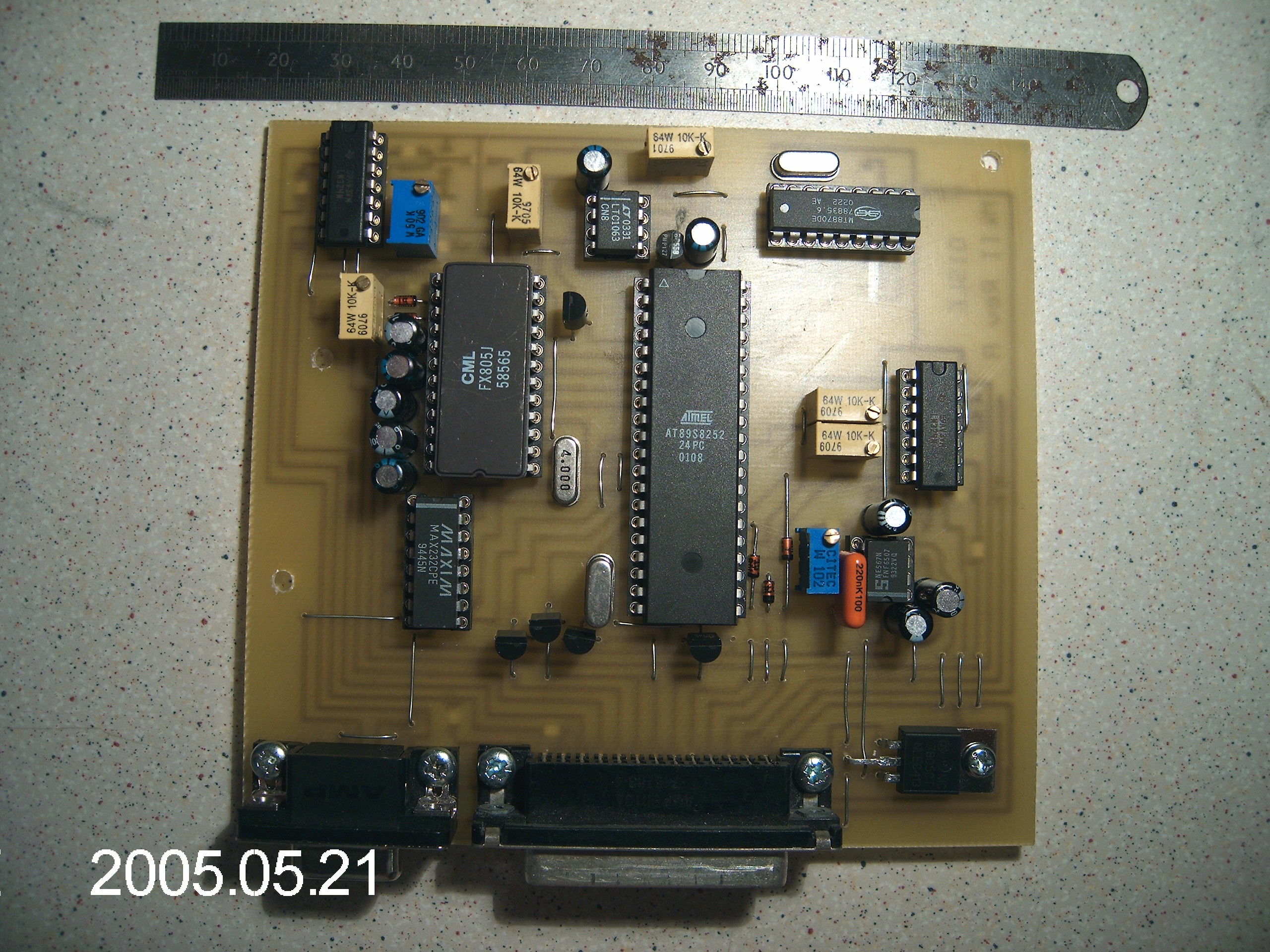
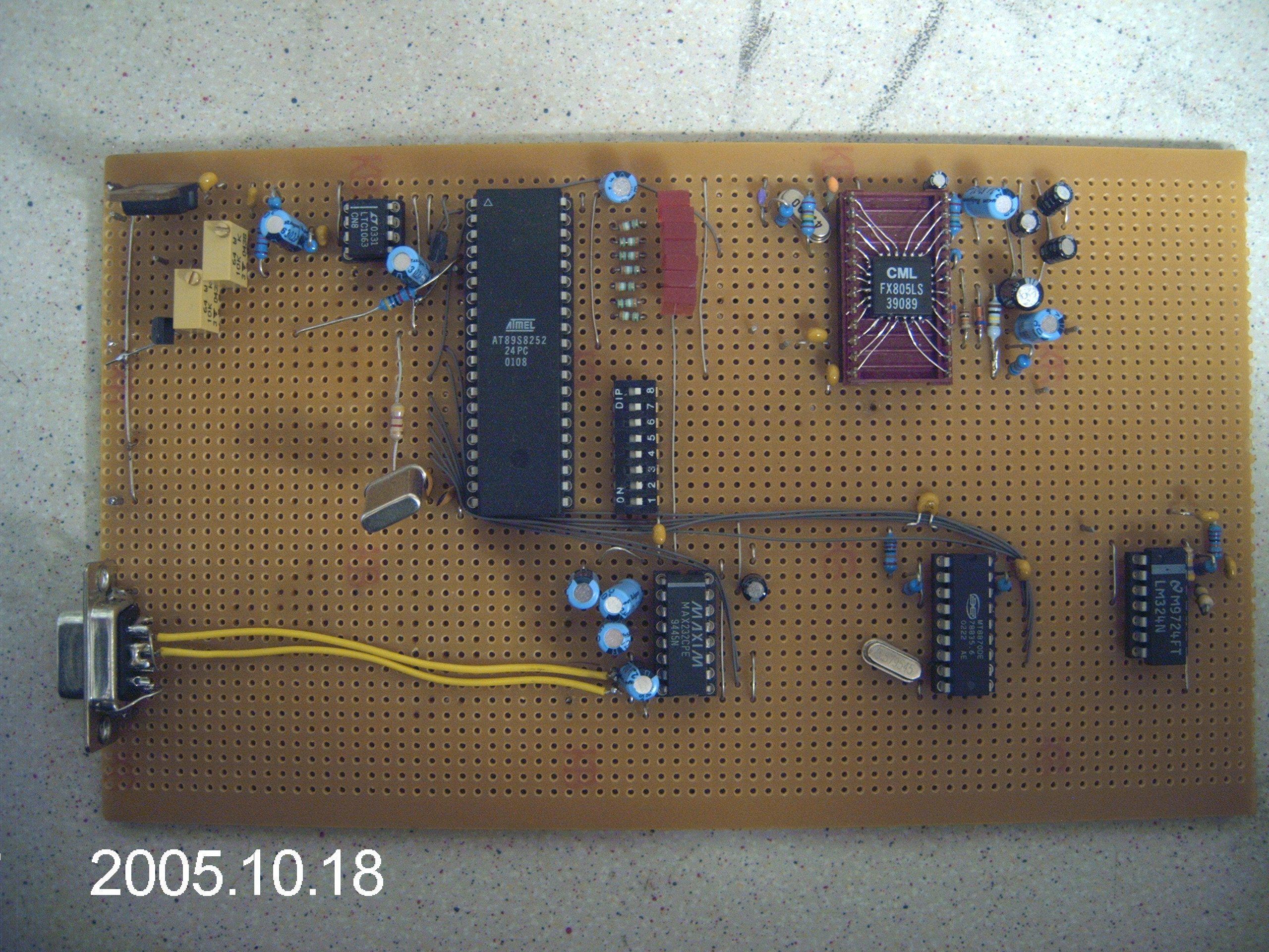
Prototype Mk2 Controller
|

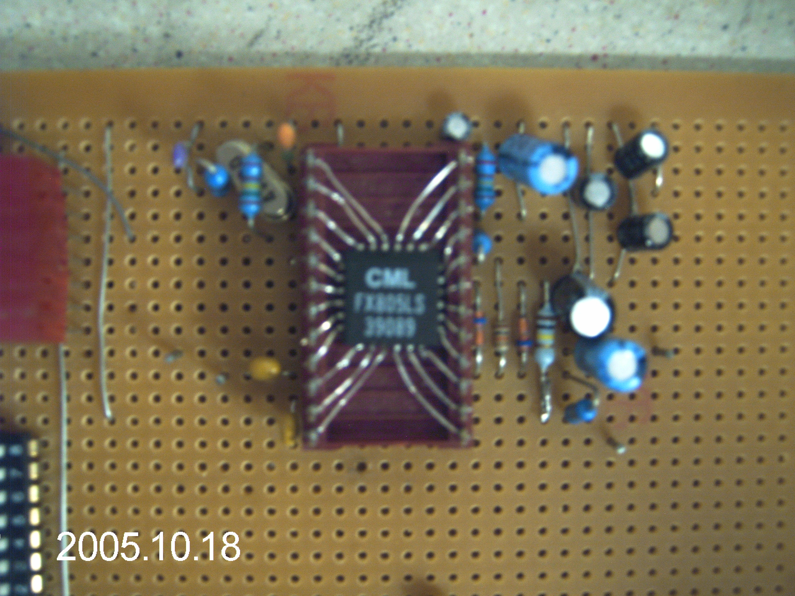
FX805 Bodge
|
This board is pretty well developed, I'm now not far of producing a 'first off' sample.
The software is pretty much done, the basic hardware is decided. As you can see from the photograph the prototype is on veroboard, the final model will be a single sided PCB employing both through board and SMT components.
The SMT will be passives only and then only 0805 and 1206 outline, nothing really small. The prototype uses a PLCC version of the FX805 bodged onto a 24 pin dil header, the final board will use the 24pin DIL version of the 805.
This new board will (amongst other things) offer:
- On board non-predictive CTCSS decoder, eliminating the need for messy external CTCSS boards
- RS232 serial port programmable by the keeper allowing the keeper to set callsign, morse pitch, morse speed, timers etc
- On board integrated DTMF remote control allowing a trusted operator with knowledge of a 4 digit PIN to switch various functions off remotely
- Legacy 1750Hz burst decoder, for those that still want it
- CTCSS decode open collector output to allow interaction with radio carrier mute control giving CTCSS users advantage in mute sensitivity compared with non-CTCSS users
Keep checking here for details of the ongoing development and before long pricing details for the finished board.
|